Modern manufacturing demands perfect quality control, but human eyes can’t catch every defect. That’s where vision systems step in to revolutionize inspection processes.
A vision system for visual inspection is an integrated machine vision system that uses optical equipment, sensors, specialized software, and computers to process and analyze images for detection, measurement, identification, and guidance tasks in manufacturing quality control.
After working with hundreds of manufacturers over the years, I’ve seen firsthand how these systems transform production lines from error-prone manual processes to precise automated operations.
What are the tools used in visual inspection?
Visual inspection relies on two main categories of tools, but which ones actually deliver results for your production line?
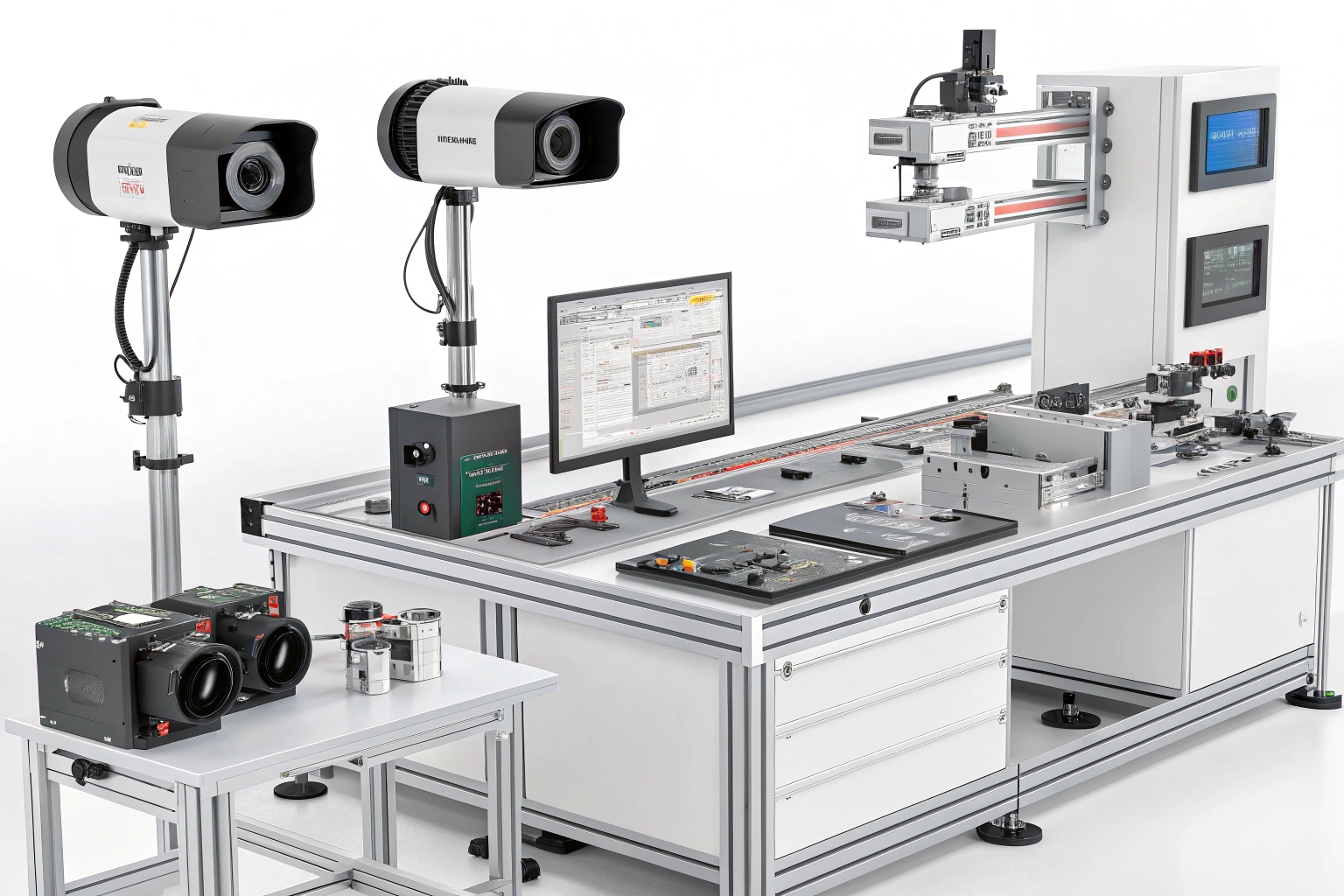
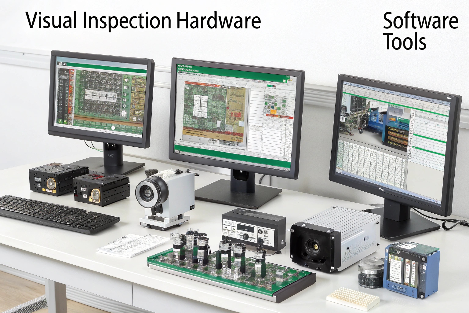
Visual inspection tools include hardware components like magnifiers, microscopes, industrial cameras, and specialized lighting, plus software tools featuring image processing algorithms for positioning, measurement, defect detection, and quality analysis.
Let me break down the essential tools I recommend to manufacturers based on their specific needs and production requirements.
Hardware Tools: The Foundation of Visual Inspection
The hardware components form the backbone of any effective visual inspection system. Here’s what I’ve found works best in real manufacturing environments:
| Tool Category | Examples | Primary Use Cases |
|---|---|---|
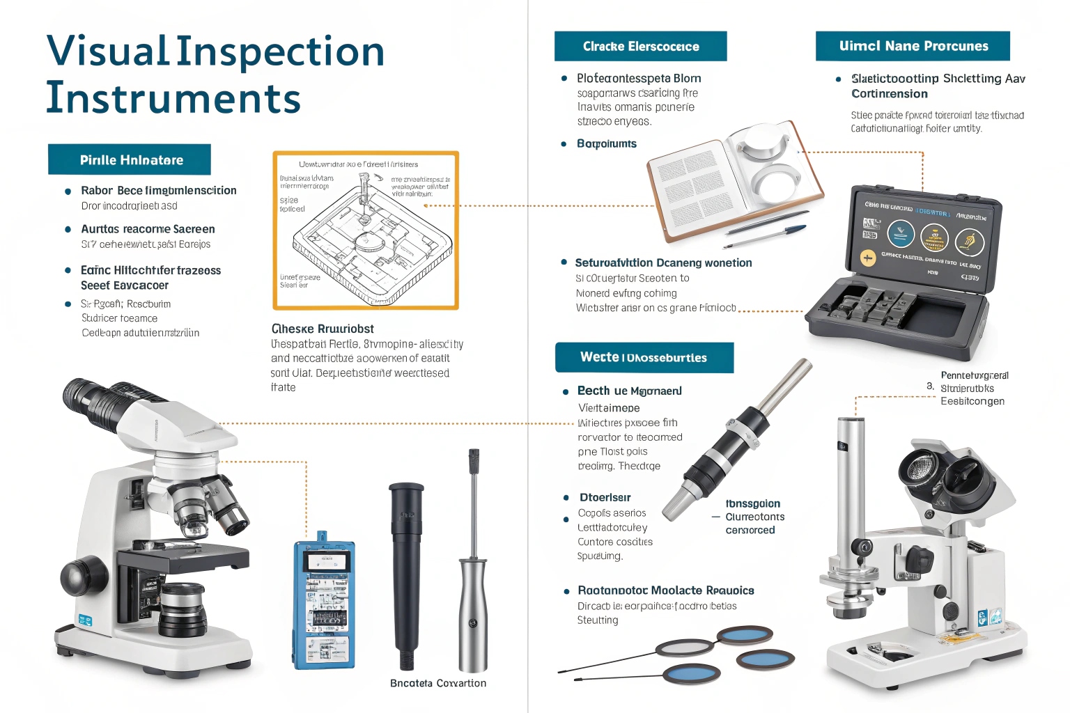
| Magnification Equipment | Industrial magnifiers, digital microscopes, stereo microscopes | Manual inspection, component verification, detailed analysis |
| Industrial Cameras | Area scan cameras, line scan cameras, smart cameras | Automated inspection, real-time monitoring, documentation |
| Lighting Systems | LED ring lights, backlight illuminators, structured light | Image enhancement, contrast optimization, 3D profiling |
| Optical Components | Telecentric lenses, macro lenses, beam splitters | Precise imaging, measurement accuracy, multi-angle viewing |
Software Tools: The Intelligence Behind Inspection
Software algorithms transform raw images into actionable quality data. The core image processing tools include positioning algorithms for precise part location, measurement tools for dimensional verification, defect detection systems for quality assessment, OCR/OCV capabilities for text and character verification, blob analysis for shape and size evaluation, and color analysis for appearance standards. These software components work together to create comprehensive inspection solutions that adapt to specific manufacturing requirements.
What instrument or tool is recommended for visual inspection?
Choosing the right inspection tool seems overwhelming, but the decision becomes clear when you match capabilities to specific requirements.
The recommended visual inspection tool depends entirely on your application, detection requirements, and budget. For simple manual checks, use magnifiers or microscopes. For automated high-volume production, implement complete machine vision systems with industrial cameras and specialized software.
Through my experience with diverse manufacturing operations, I’ve developed a practical framework for tool selection that saves both time and money.
Application-Based Tool Recommendations
For simple, macroscopic manual inspection tasks, I recommend starting with magnifiers or microscopes. These represent the most economical and direct approach for basic quality checking. They’re perfect for prototype development, small-batch production, or detailed failure analysis where human expertise adds value.
For repetitive, high-volume automated online inspection, complete machine vision systems become essential. These systems include industrial cameras, specialized lighting, precision lenses, and vision processing software. This configuration represents the standard for modern industrial production where consistency and speed matter most.
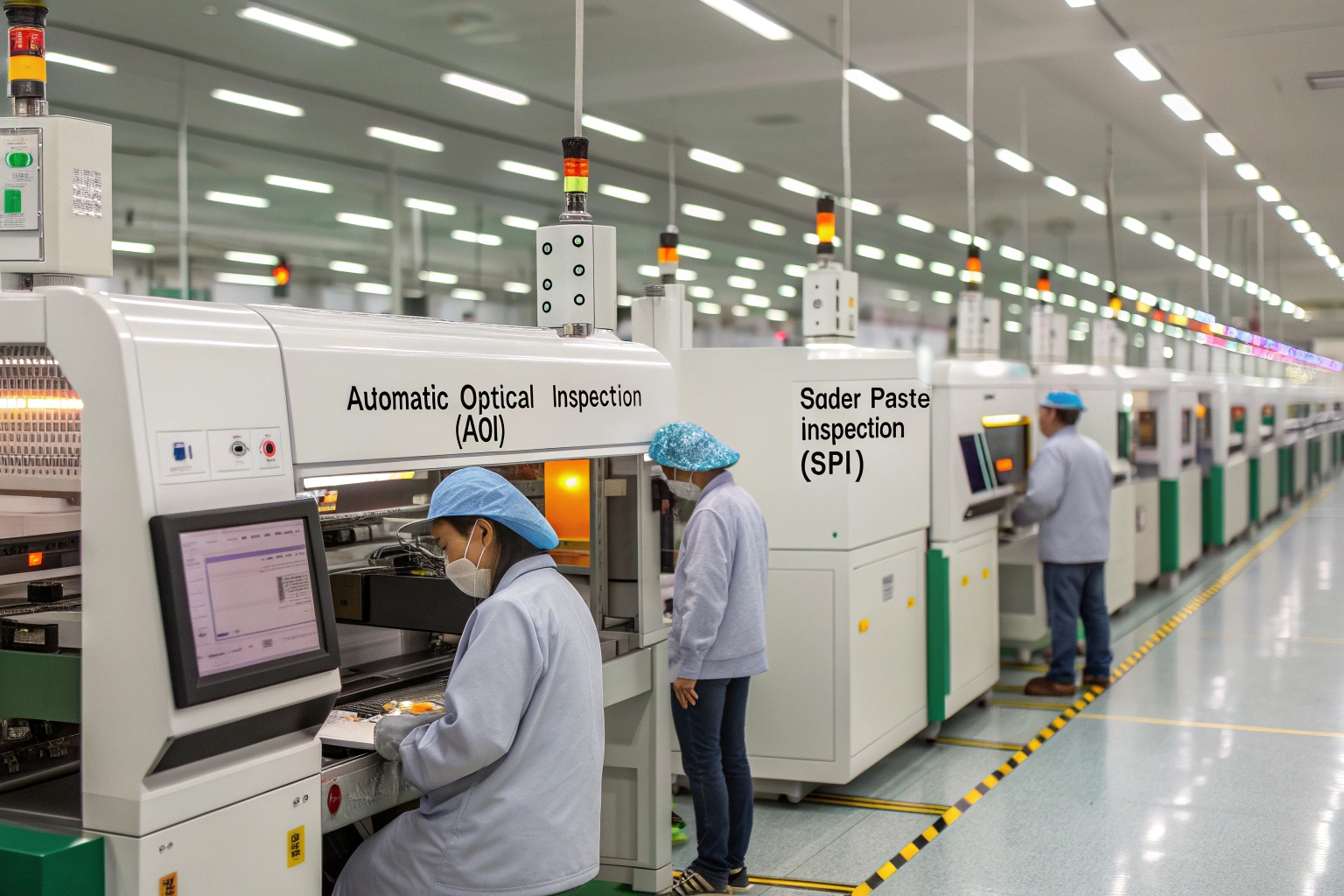
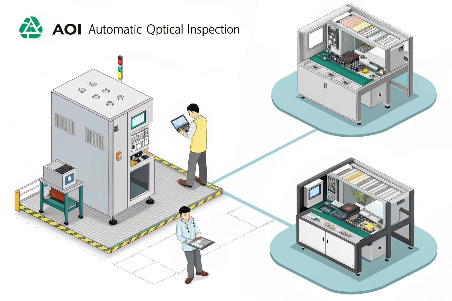
For specific industry applications, specialized equipment delivers optimal results. In electronics manufacturing, particularly PCB and SMT operations, Automated Optical Inspection (AOI) machines provide unmatched capability. For welding quality assessment, three-dimensional AOI systems excel at detecting complex defects. For solder paste printing validation, Solder Paste Inspection (SPI) machines offer specialized functionality that general-purpose systems cannot match.
What are the different types of AOI systems?
AOI technology has evolved rapidly, but understanding the key differences helps you choose the right system for your production needs.
AOI systems are categorized by technology dimension (2D vs 3D) and installation method (inline, offline, desktop). 2D AOI uses flat images for basic detection while 3D AOI adds height measurement for comprehensive analysis. Installation types range from integrated production line systems to flexible standalone units.
Let me explain the practical implications of each AOI type based on real manufacturing scenarios I’ve encountered across different industries.
Technology Dimension Classifications
2D AOI systems use two-dimensional image analysis for component detection. They excel at identifying component presence or absence, placement offset, rotation angles, polarity orientation, and part number verification. These systems offer lower costs and simpler operation, making them suitable for most routine inspection tasks in electronics manufacturing.
3D AOI systems incorporate height information through laser triangulation, structured light projection, or multi-angle camera arrays. Beyond standard 2D capabilities, they measure component height variations, detect warpage issues, verify pin coplanarity, and analyze three-dimensional solder joint shapes and volumes. This enhanced detection capability comes with higher precision and cost, but delivers superior defect catching rates for critical applications.
Installation and Application Methods
Inline AOI systems integrate directly into production lines for 100% real-time inspection of every board. They serve as core quality control checkpoints, providing immediate feedback for process adjustments and defect prevention. These systems maximize throughput while maintaining consistent quality standards.
Offline AOI systems operate beside production lines for sampling inspection, failure analysis, or program development. They offer operational flexibility without disrupting production flow, making them ideal for quality audits and process optimization studies.
Desktop AOI systems target research environments, laboratories, or small-batch production settings. They provide full inspection capability in compact formats suitable for limited space applications or specialized testing requirements.
What is the difference between AOI and SPI?
Many manufacturers confuse AOI and SPI systems, but they serve completely different inspection stages in electronics assembly.
AOI and SPI are both critical SMT inspection systems, but SPI inspects solder paste after printing and before component placement, while AOI inspects components and solder joints after reflow soldering. They target different process stages with distinct detection objectives.
Understanding when and why to use each system has helped me guide manufacturers toward more effective quality control strategies.
Comprehensive Comparison Analysis
| Feature | SPI (Solder Paste Inspection) | AOI (Automated Optical Inspection) |
|---|---|---|
| Inspection Target | Solder paste after printing | Components and joints after reflow |
| Process Position | After paste printer, before pick-and-place | After reflow oven |
| Detection Focus | Paste thickness, volume, area, offset, bridging | Component presence, placement, joint quality |
| Core Technology | Primarily 3D measurement (laser, moiré) | Both 2D and 3D technologies available |
| Primary Purpose | Preventive detection before expensive processes | Final quality verification and control |
| Process Control Role | Foundation quality assurance | Comprehensive final inspection |
Strategic Implementation Differences
SPI systems function as preventive quality measures, catching solder paste defects before components are placed and processed through expensive reflow operations. They focus specifically on print quality parameters including paste height uniformity, volume accuracy, area coverage, position precision, and bridging prevention. This early detection prevents defective boards from consuming valuable production resources.
AOI systems provide comprehensive final inspection after all assembly processes complete. They verify component installation accuracy, solder joint integrity, and overall assembly quality. Their detection scope covers component presence verification, placement accuracy, orientation correctness, polarity validation, and complete joint quality assessment including bridging, insufficient solder, and solder ball detection.
The relationship between these systems creates a complete quality control framework. SPI establishes the foundation by ensuring proper solder paste application, while AOI validates the final assembly results. Together, they provide comprehensive process control from initial paste application through final product verification, maximizing yield while minimizing defect escape rates.
Conclusion
Vision systems revolutionize manufacturing quality control through integrated hardware, software, and strategic implementation approaches that transform inspection from manual processes to automated precision operations.
Written by

You may also be interested in:

What is the Best Optical Sorter?
You stare at dozens of optical

How Does Visual Inspection Work?
Every manufacturer faces quali